
The first year of KONFLOT has focused on the preparation of the case studies in which the co-design methodology will be tested, and the generation of material and knowledge necessary for its application.
The floating wind energy and wave energy case studies have been fully defined, for which work has been carried out on the definition of:
- Wind turbine and platform typology; wave energy collector.
- Components of the system to be optimised: tower, platform and moorings; collector, PTO and moorings.
- Specific variables to be optimised in each subsystem.
- Location for the case study
- Load cases
The best implementation strategy for the design and control iterations has also been defined up to the definition of a methodology that is being integrated into a software tool. In this phase, reduced models have been developed to accelerate the first steps of the co-design, and high-level models have been defined against which the results will be validated.
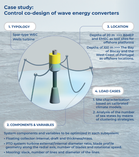
Control co-design of wave energy converters
The main objective is to design and develop a control co-design (CCD) methodology for the optimisation of wave energy harvesters that considers the most relevant aspects from the initial design stage. This methodology will be designed in a generic way, to ensure possible implementation in any wave energy system, but validated for a case study endorsed by the KONFLOT Advisory Board: Oscillating Water Column (OWC) floating system.
In the selected strategy for the co-design methodology for the wave catcher there are two optimisation loops: (i) outer loop dedicated to the optimal selection of design parameters and (ii) inner loop oriented to energy maximisation through optimal control strategies.
Definition of the case study for wave energy
The case study has been included in the wave energy systems based on the OWC principle, due to the characteristics of the industrial and research fabric of the Basque Country, where there is both a worldwide reference technology developer and a unique infrastructure dedicated to this type of technology. Furthermore, the specific device selected for the development of the CCD methodology is a floating sensor for which there is a large amount of public information: Sparbuoy OWC.
- Typology of wave energy collector
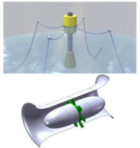
Collector and turbine of the OWC selected system
This collector consists of a generic spar-type device divided into three main parts: a cylindrical upper part, a cylindrical central part also cylindrical but much more elongated, and a semi-conical lower part. As for the turbine of the PTO system, it has been established that it must be symmetrical in order to be able to operate with bi-directional air flows. Due to the complexity of this type of system, the case study is limited to the analysis of Wells type turbines, which are the most common for OWC systems. However, it is expected to analyse different configurations of Wells turbines, including those that allow active control. Finally, it has been defined that the Mooring system will have between three and four mooring lines.
- System components to be optimised
The characterisation of the system is divided into two parts, for which numerical behaviour prediction models have been defined. Thus, these models are divided into two: those referring to the collector and those referring to the PTO system. In both cases, two types of models have been defined, one more accurate but computationally heavier, and the other computationally much more efficient, but less accurate in capturing the different dynamics of the systems:
-
- The spar floater
- The PTO system
- Mooring lines
- Variables to be optimised in each subsystem
The selection of the parameters and metrics used for the evaluation of the different configurations of both the collector and the turbine has been carried out independently:
-
- Floating collector: internal diameters (top and bottom), draft and thickness/mass.
- PTO system: turbine external/internal diameter ratio, blade profile geometry along the radial axis, number of blades and rotational speed.
- Mooring: slack, number of lines and diameter of the lines.
- Location for the case study
Different locations have been defined based on the depth of the site. On the one hand, for medium depths of 20 metres, BiMEP and EMEC have been chosen as test sites for offshore platforms. On the other hand, for average depths of 100 metres, the Bay of Biscay and the West Coast of Portugal (Atlantic) have been selected as offshore locations.
- Load cases
Load cases have been defined, which are limited to energy production conditions (normal operation). The first, site characterisation based on calibrated climate models, and the second, analysis of the number of sea states by means of clustering strategies.