
The first year of KONFLOT has focused on the preparation of the case studies in which the co-design methodology will be tested, and the generation of material and knowledge necessary for its application.
The floating wind energy and wave energy case studies have been fully defined, for which work has been carried out on the definition of:
- Wind turbine and platform typology; wave energy collector.
- Components of the system to be optimised: tower, platform and moorings; collector, PTO and moorings.
- Specific variables to be optimised in each subsystem.
- Location for the case study.
- Load cases.
- Control strategies
The best implementation strategy for the design and control iterations has also been defined until the definition of a methodology that is being integrated into a software tool. In this phase, reduced models have been developed to accelerate the first steps of the co-design, and high-level models have been defined against which the results will be validated.
Control co-design in floating wind turbines
In the first year, work has been carried out on the preparation of a case study to test the control co-design methodology (CCD) in floating wind turbines. A flexible and modular tool is being developed to validate the methodology through a case study in the framework of the KONFLOT project, and to facilitate its future adaptation to test other cases (other topologies, controls, design variables, location conditions or target metrics) different from those selected in this first phase.
It has been considered that the nested CCD is more suitable for its application in KONFLOT, so the design methodology will perform in each iteration a first optimisation of the plant parameters to subsequently adjust the appropriate control parameters to this design. Once the methodology has been established, the most appropriate control strategies have been identified.
Definition of the case study for floating wind turbines
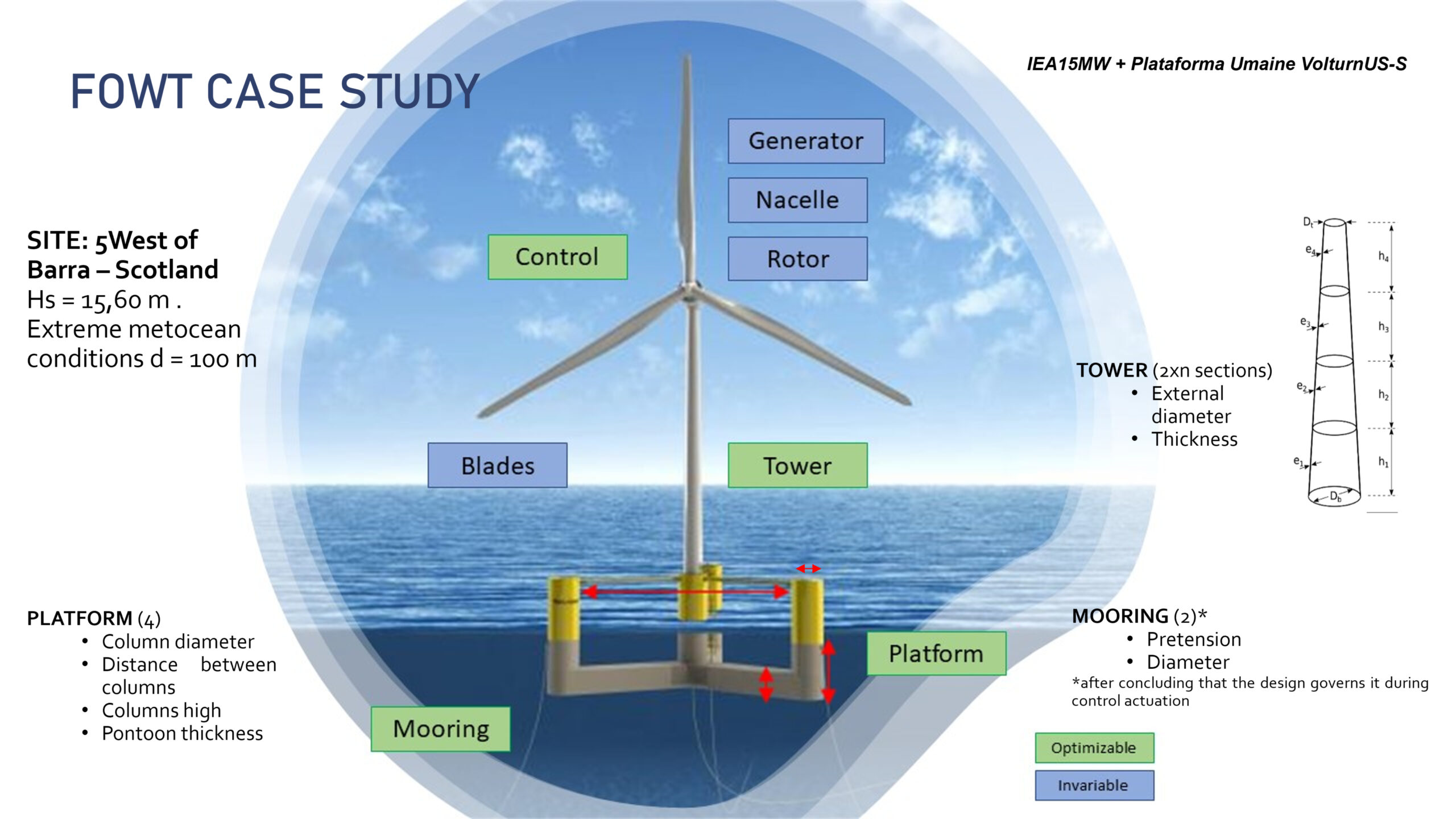
Although the CCD methodology considers all subsystems, their dynamics and interaction with each other, it is computationally overly complex and beyond the scope of the KONFLOT project. To validate the effectiveness of the methodology, it has been decided to work on the platform subsystem. This decision is justified given the number of platform manufacturers we have at national level and in the Basque Country in particular. A public model has been selected on which to apply the methodology and validate the tools generated, which, due to the trend in the offshore wind market and the fact that it is a publicly accessible model, is the UMaine VolturnUS-S platform.
- Type of wind turbine and platform
General properties of the floating wind turbine system
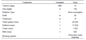
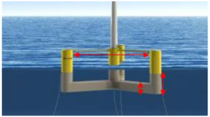
The semi-submersible platform consists of a tri-column (120º) steel float with a centred tower, passive ballast and three mooring lines, while the wind turbine installed is a horizontal axis turbine with a power of 15 MW (public model IEA15MW).
- System components to be optimised
To determine which subsystems of the plant will enter the optimisation loop and which will not, a justification exercise has been carried out, evaluating criteria of complexity of the models to be developed vs. impact on the target metrics. The results that have been concluded are as follows:
-
- The tower and float subsystems are optimisable due to their influence both on the total costs and on the dynamics of the whole.
- The control is conditioned to be adjusted for each of the plant designs to maximise the power output without harming the loads, so it is also considered as an optimisable subsystem.
- The mooring subsystem has been considered optimisable after performing a time domain analysis using the OpenFAST public model. The maximum stresses at the anchor points have been occurred in the case of Extreme Operating Conditions loads where control has an influence.
- Variables to be optimised in each subsystem
Platform optimisation variables
A preliminary analysis of the influence of the different parameters of each subsystem that affect the dynamics of the FOWT has been carried out and the following optimisation variables have been defined for the first version of the tool:
-
- Platform: Column diameter, column axis radius, draught and pontoon thickness.
- Tower: Diameter and thickness distribution
- Mooring: Length/pretension and Diameter.
- Control: Control strategy (each strategy has different parameters to be tuned).
In order to carry out the optimisation, we are working on the definition of an objective function where some metrics are evaluated that will have flexible weights to be particularised in each case.
- Location for the case study

Location of the FOWT case study
The selected location for the wind turbine is west of the Isle of Barra, Scotland. The site has been chosen for its extreme conditions. The platform will be characterised for LIFE50+ meteoceanic conditions.
- Load cases
As for the models that will represent the dynamics of the FOWT, two characterisations have been developed in parallel:
-
- OPENFAST model. The following load cases have been simulated: DLC 1.2 (Fatigue) Normal operating conditions, DLC 1.6 Extreme operating conditions and DLC 6.1 Survival conditions.
- REDUCED model: a reduced dynamic model has been developed for use in both optimisation and control strategy development.
Both models will communicate via a tool that allows the simulation model to be exchanged between the reduced model and the OpenFAST model. In this way, the CCD methodology can be carried out using the reduced model in order to subsequently validate the result obtained with a more complex model such as OpenFAST.